PRODUCTS DETAIL_
VM-3000 Series
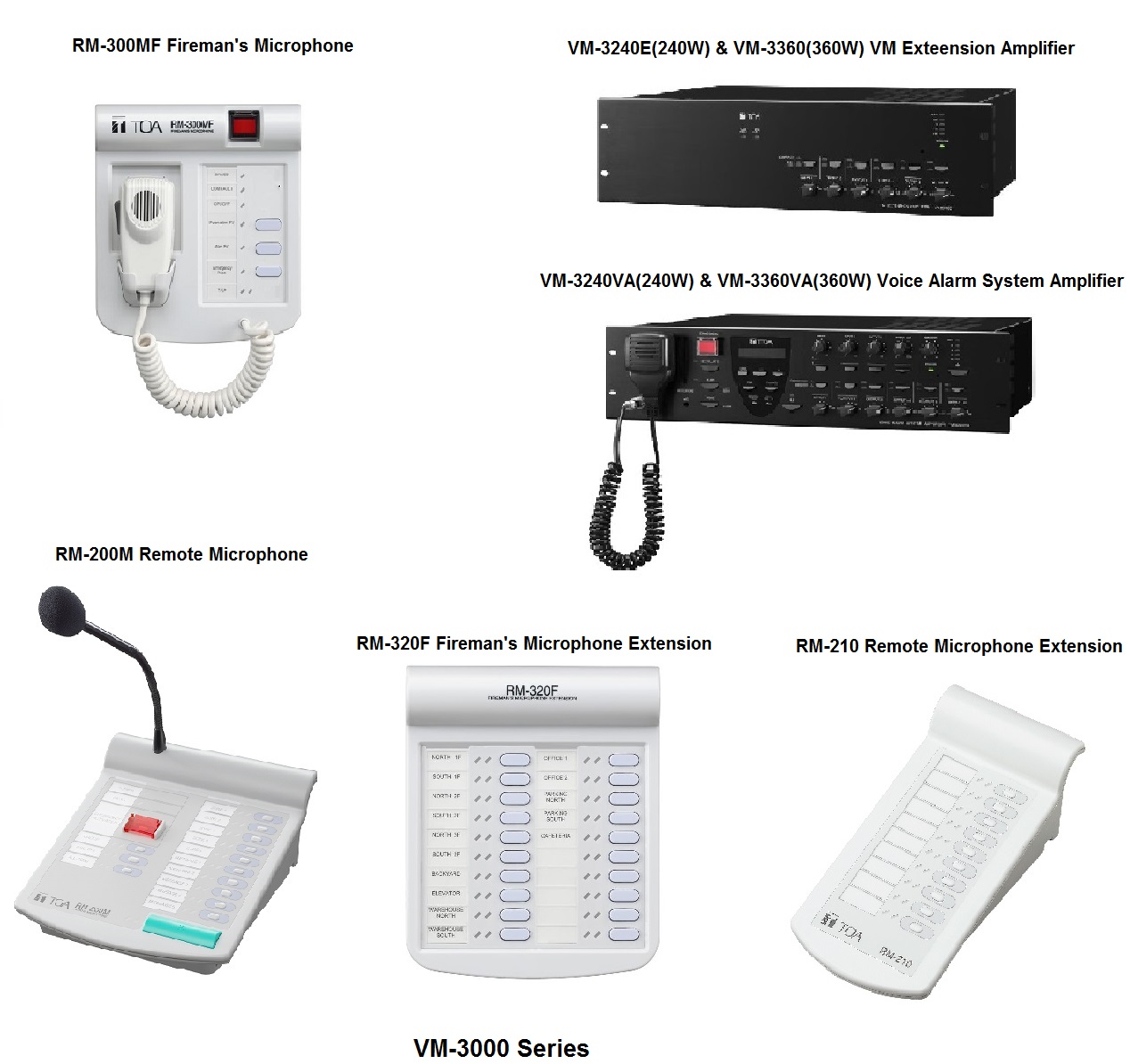
VM-3000 Series
Voice Alarm System Amplifier VM-3240VA(240W) and VM-3360(360W)
Specification
|
Model |
VM-3240VA(240W) |
VM-3360(360W) |
|
Power Source |
230 V AC, 50/60 Hz |
230 V AC, 50/60 Hz |
|
Power Consumption |
600 W (with rated output signal), 260 W (according to EN60065) |
850 W (with rated output signal), 380 W (according to EN60065 |
|
Rated Output |
240 W |
360 W |
|
Frequency Response |
50 Hz - 20 kHz,3 dB (at 1/3 rated output) |
50 Hz - 20 kHz,3 dB (at 1/3 rated output) |
|
Distortion |
0.7 % or less (at rated output, 1 kHz) |
0.7 % or less (at rated output, 1 kHz) |
|
S/N Ratio |
85 dB or more |
85 dB or more |
|
Audio Input/Output Characteristic |
Sampling frequency: 48 kHz |
Sampling frequency: 48 kHz |
|
Input |
Input 1 - 3: -50 dB* (MIC)/-10 dB* (LINE) (changeable), 600 Ω, |
Input 1 - 3: -50 dB* (MIC)/-10 dB* (LINE) (changeable), 600 Ω, |
|
Output |
Speaker output 1 - 2: Max. (240 W) per output |
Speaker output 1 - 2: Max. (360 W) per output |
|
RM Link |
Input 1 - 2: Connecting the RM-300MF/RM-200M Remote Microphone. |
Input 1 - 2: Connecting the RM-300MF/RM-200M Remote Microphone. |
|
Network I/F |
10BASE-T / 100BASE-TX (selectable by automatic negotiation), RJ45 female connector |
10BASE-T / 100BASE-TX (selectable by automatic negotiation), RJ45 female connector |
|
VM Link |
Output: Connecting the VM-3240E or VM-3360E, RJ45 female connector |
Output: Connecting the VM-3240E or VM-3360E, RJ45 female connector |
|
EXT PA Link |
Connecting the VP-2241 or VP-2421, RJ45 female connector |
Connecting the VP-2421, RJ45 female connector |
|
General Control |
Input 1 - 8: No-Voltage make contact input, open voltage: 24 V DC, |
Input 1 - 8: No-Voltage make contact input, open voltage: 24 V DC, |
|
Emergency Control |
Input 1 - 5: No-Voltage make contact input, open voltage: 24 V DC, |
Input 1 - 5: No-Voltage make contact input, open voltage: 24 V DC, |
|
ATT Control |
Relay contact 1-6, 125 V AC or 30 V DC, total under 5 A, |
Relay contact 1-6, 125 V AC or 30 V DC, total under 5 A, |
|
Power Input/Output |
Power in: Connecting the VX-2000DS only (operating range: 20 - 40 V DC) |
Power in: Connecting the VX-2000DS only (operating range: 20 - 40 V DC) |
|
DC24V Output |
24 V DC, Maximum feeding current 0.3 A |
24 V DC, Maximum feeding current 0.3 A |
|
Ds Link |
Connecting the VX-2000DS, RJ45 female connector |
Connecting the VX-2000DS, RJ45 female connector |
|
Operating Temperature |
-5 ℃to +45 ℃(23 ゜F to 113 ゜F) |
-5 ℃to +45 ℃(23 ゜F to 113 ゜F) |
|
Operating Humidity |
5 % to 95 %RH (no condensation) |
5 % to 95 %RH (no condensation) |
|
Finish |
Panel: Aluminum, hairline, black |
Panel: Aluminum, hairline, black |
|
Dimensions |
482 (W) 132.6 (H) 431.2 (D) mm (18.98" 5.22" 16.98") |
482 (W) 132.6 (H) 431.2 (D) mm (18.98" 5.22" 16.98") |
|
Weight |
16.5 kg (36.38 lb) |
19 kg (41.89 lb) |
|
Accessory |
Power cable (2 m (6.56 ft)) …1, Setting software-CD …1, Link cable (3 m (9.84 ft)) …2, |
Power cable (2 m (6.56 ft)) …1, Setting software-CD …1, Link cable (3 m (9.84 ft)) …2, |
|
Option |
Input transformer: IT-450 |
Input transformer: IT-450 |
VM Extension Amplifier VM-3240E(240W) and VM-3360E(360W)
Specification
|
Model |
VM-3240E(240W) |
VM-3360E(360W) |
|
Power Source |
230 V AC, 50/60 Hz |
230 V AC, 50/60 Hz |
|
Power Consumption |
600 W (with rated output signal), 260 W (according to EN60065) |
850 W (with rated output signal), 380 W (according to EN60065) |
|
Rated Output |
240 W |
360 W |
|
Frequency Response |
50 Hz - 20 kHz, 3 dB (at 1/3 rated output) |
50 Hz - 20 kHz, 3 dB (at 1/3 rated output) |
|
Distortion |
0.7 % or less (at rated output, 1 kHz) |
0.7 % or less (at rated output, 1 kHz) |
|
S/N Ratio |
85 dB or more |
85 dB or more |
|
Input |
External amplifier input: 100 V line, removable terminal block (14 pins) |
External amplifier input: 100 V line, removable terminal block (14 pins) |
|
Output |
Speaker output 1 - 2: Max. (240 W) per output |
Speaker output 1 - 2: Max. (360 W) per output |
|
VM Link |
Input: Connecting the VM-3240VA or VM-3360VA, RJ45 female connector |
Input: Connecting the VM-3240VA or VM-3360VA, RJ45 female connector |
|
EXT PA Link |
Connecting the VP-2241, RJ45 female connector |
Connecting the VP-2421, RJ45 female connector |
|
General Control |
Input 1 - 8: No-Voltage make contact input, open voltage: 24 V DC, |
Input 1 - 8: No-Voltage make contact input, open voltage: 24 V DC, |
|
Emergency Control |
Input 1 - 5: No-Voltage make contact input, open voltage: 24 V DC, |
Input 1 - 5: No-Voltage make contact input, open voltage: 24 V DC, |
|
ATT Control |
Relay contact 1-6, 125 V AC or 30 V DC, total under 5 A, |
Relay contact 1-6, 125 V AC or 30 V DC, total under 5 A, |
|
Power Input/Output |
Power in: Connecting the VX-2000DS only (operating range: 20 - 40 V DC) |
Power in: Connecting the VX-2000DS only (operating range: 20 - 40 V DC) |
|
DC24V Output |
24 V DC, Maximum feeding current 0.3 A |
24 V DC, Maximum feeding current 0.3 A |
|
Ds Link |
Connecting the VX-2000DS, RJ45 female connector |
Connecting the VX-2000DS, RJ45 female connector |
|
Operating Temperature |
-5 ℃to +45 ℃(23 ゜F to 113 ゜F) |
-5 ℃to +45 ℃(23 ゜F to 113 ゜F) |
|
Operating Humidity |
5 % to 95 %RH (no condensation) |
5 % to 95 %RH (no condensation) |
|
Finish |
Panel: Aluminum, hairline, black |
Panel: Aluminum, hairline, black |
|
Dimensions |
482 (W) 132.6 (H) 407 (D) mm (18.98" 5.22" 16.02") |
482 (W) 132.6 (H) 407 (D) mm (18.98" 5.22" 16.02") |
|
Weight |
16.5 kg (36.38 lb) |
19 kg (41.89 lb) |
|
Accessory |
Power cable (2 m (6.56 ft)) …1, Link cable (3 m (9.84 ft)) …2, |
Power cable (2 m (6.56 ft)) …1, Link cable (3 m (9.84 ft)) …2, |
VM-3000 Series Microphones and Optional Accessories
RM-300MF Fireman's Microphone and RM-200M Remote Microphone
Specification
|
Model |
RM-300MF Fireman’s Microphone |
RM-200M Remote Microphone |
|
Power Source |
24 V DC (operating range: 15 - 40 V DC, supplied from the VM-3000 system) |
24 V DC (Operating range: 14 - 28 V DC) |
|
Current Consumption |
120 mA (RM-300MF), 660 mA (with 3 RM-320F connected) |
100 mA or less |
|
Audio Output |
_ |
0 dB(*1) |
|
Frequency Response |
200 Hz - 15 kHz |
100 - 20 |
|
Distortion |
1 % or less |
1% or less |
|
S/N Ratio |
55 dB or more |
60 dB or more |
|
Microphone |
Unidirectional dynamic microphone with talk key, compressor (on/off switchable) |
Unidirectional electret condenser microphone |
|
No. of Function Keys |
_ |
13 |
|
Emergency Broadcast(*3) |
_ |
Activation of Emergency Broadcast (pre-recorded announcement or live |
|
Volume Control |
Microphone volume control, Buzzer volume control |
Microphone volume control |
|
Connection Cable and Connector |
Main line: Shield CPEV cable (each one pair of Audio line, Data line, Power supply line) |
Category 5 STP cable, RJ45 Connector |
|
Maximum Cable Distance |
Total 800 m (874.89 yd) |
500m (Free topology wiring) |
|
No. of Connectable RM-320F |
Max. 3 units |
_ |
|
Operation |
Emergency key, Evacuate key, Alert key, Emergency reset key, CPU switch, Reset switch |
_ |
|
Indicator |
Power indicator, Emergency indicator, Communication failure indicator, CPU OFF indicator, |
_ |
|
Operating Temperature |
-5 ℃to +45 ℃(23 ゜F to 113 ゜F) |
-5 ℃to +45 ℃(23 ゜F to 113 ゜F) |
|
Operating Humidity |
5 % to 95 %RH (no condensation) |
5 % to 95 %RH (no condensation) |
|
Finish |
ABS resin, blueish gray (PANTONE 538 or its equivalent) |
ABS resin, blueish gray (PANTONE 538 or its equivalent) |
|
Dimensions |
200 (W) 215 (H) 82.5 (D) mm (7.87" 8.46" 3.25") |
200 (W) 215 (H) 82.5 (D) mm (7.87" 8.46" 3.25") |
|
Weight |
1.1 kg (2.43 lb) (with wall mounting bracket unit) |
1.1 kg (2.43 lb) (with wall mounting bracket unit) |
|
Accessory |
Wall mounting bracket unit…1, Wall mounting screw…2 |
Wall mounting bracket unit…1, Wall mounting screw…2 |
RM-320F Fireman’s Microphone Extension and RM-210 Remote Microphone Extension
Specification
|
Model |
RM-320F Fireman’s Microphone Extension |
RM-210 Remote Microphone Extension |
|
Current Consumption |
180 mA max. (in terms of RM-300MF) |
20 mA max. (in terms of RM-200M's DC power input) |
|
Connection |
Connection to RM-300MF by dedicated cable |
Connection by way of dedicated cable |
|
Number of Function Keys |
20 |
10 |
|
Finish |
ABS resin, blueish gray (PANTONE 538 or its equivalent) |
ABS resin, blueish gray (PANTONE 538 or its equivalent) |
|
Dimensions |
175 (W) 215 (H) 70 (D) mm (6.89" 8.46" 2.76") |
110 (W) 76.5 (H) 215 (D) mm |
|
Weight |
700 g (1.54 lb) |
350 g |
|
Accessory |
Wall mounting bracket…1, Wall mounting screw…2 |
Extension cable ……1, Linkage bracket A ……2, Linkage bracket B ……1, |
|
Applicable Unit (option) |
_ |
RM-200M, RM-200SA, RM-200SF, RM-200X, RM-200XF |